Stage 2. ER Diagrams Basics: Design Before CREATE TABLE
Beginners often start database design by writing CREATE TABLE immediately. It feels productive: you create users, then orders, then products, and the schema starts to exist. The problem appears a month later, when relationships are unclear, fields are duplicated, and every new feature requires guessing where data should live.
An ER diagram prevents this. It is a blueprint of the database before the database is created. First you draw the business objects and their relationships. Only after that do you turn the model into SQL tables, columns, foreign keys, and join tables.
What an ER Diagram Is
ER means Entity-Relationship. It describes three basic things:
| ER term | Meaning | What it becomes in SQL |
|---|---|---|
| Entity | Business object in the domain | Table |
| Attribute | Data stored about an entity | Column |
| Relationship | Connection between entities | Foreign key or join table |
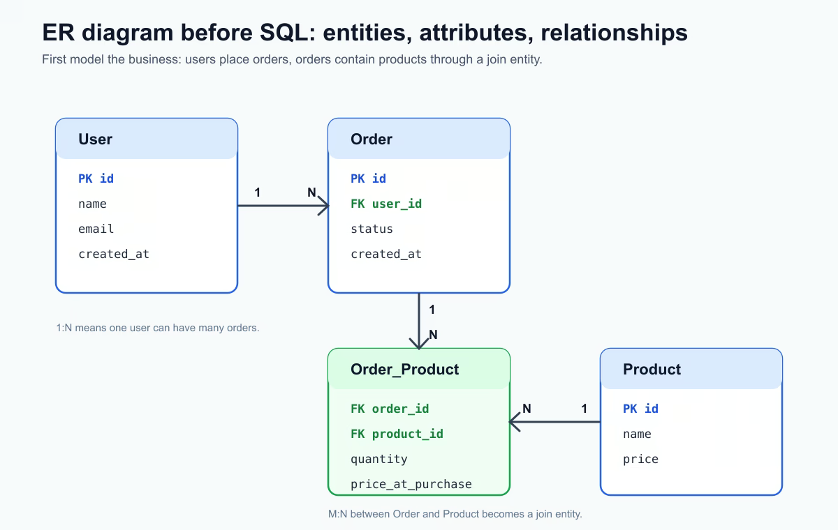
For an online shop, typical entities are User, Order, and Product. At this stage they are not SQL tables yet. They are objects from the business domain: a user places orders, an order contains products, and a product can appear in many orders.
Entity: the Future Table
An entity is a thing the system needs to remember separately. User is an entity because the system stores user identity and contact data. Order is an entity because the system stores purchase events. Product is an entity because the catalog has products with names, prices, and availability.
The useful test is this: can you describe the responsibility of the entity in one sentence? If not, it may be too vague or it may contain several different concepts mixed together.
Attributes: the Future Columns
Attributes describe what data belongs to an entity. For User, a simple set of attributes might be:
id;name;email;created_at.
Later these attributes become table columns. The ER diagram does not need to contain every technical detail from the final migration, but it should show the important fields that define the model: identifiers, names, timestamps, statuses, and fields that participate in relationships.
Relationships: the Most Important Part
Relationships show how records connect. This is where many beginners finally understand why databases are not just isolated tables.
| Type | Example | How it looks in the database |
|---|---|---|
| 1:1 | User - Profile | Foreign key in one of the tables |
| 1:N | User - Order | orders.user_id points to users.id |
| M:N | Order - Product | Intermediate table such as order_products |
Cardinality is the “how many?” part of the relationship. Ask practical questions instead of memorizing notation. Can one user have many orders? Yes, so User to Order is 1:N. Can one order contain many products, and can one product appear in many orders? Yes, so Order to Product is M:N. A relational database represents M:N through a join table.
From ER to SQL
The transformation is direct:
| ER model | SQL implementation |
|---|---|
| Entity | Table |
| Attribute | Column |
| Relationship | Foreign key |
| M:N relationship | Join table |
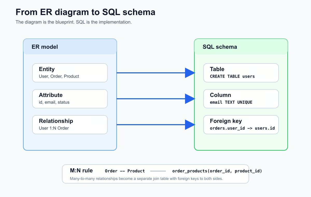
For the online shop model, the diagram:
User --< Order --< Order_Product >-- Product
turns into these tables:
CREATE TABLE users (
  id BIGSERIAL PRIMARY KEY,
  name TEXT NOT NULL,
  email TEXT UNIQUE NOT NULL,
  created_at TIMESTAMP NOT NULL DEFAULT NOW()
);

CREATE TABLE orders (
  id BIGSERIAL PRIMARY KEY,
  user_id BIGINT NOT NULL REFERENCES users(id),
  status TEXT NOT NULL,
  created_at TIMESTAMP NOT NULL DEFAULT NOW()
);

CREATE TABLE products (
  id BIGSERIAL PRIMARY KEY,
  name TEXT NOT NULL,
  price NUMERIC(10,2) NOT NULL
);

CREATE TABLE order_products (
  order_id BIGINT NOT NULL REFERENCES orders(id),
  product_id BIGINT NOT NULL REFERENCES products(id),
  quantity INTEGER NOT NULL,
  price_at_purchase NUMERIC(10,2) NOT NULL,
  PRIMARY KEY (order_id, product_id)
);
order_products exists because the relationship between orders and products is many-to-many. It also stores relationship-specific facts: quantity and price at the moment of purchase. These values do not belong only to orders or only to products; they describe the product inside a specific order.
Mistakes ER Diagrams Prevent
Without an ER diagram, common design mistakes appear quickly:
- Duplicating user or product data in many tables.
- Creating wrong relationships, such as storing only one product directly in
orders. - Making future joins harder because foreign keys are unclear.
- Breaking normalization later because responsibilities were never separated.
- Forgetting cardinality and optional relationships.
Drawing the model first does not remove all design work, but it makes the questions visible before migrations and application code depend on a weak schema.
Tools You Can Use
For practice, start with simple tools:
dbdiagram.iofor quick database-style diagrams;draw.iofor flexible visual sketches;- DBeaver for viewing diagrams from an existing database.
Choose the tool that helps you think clearly. The important part is not the tool, but the discipline: relationships first, SQL second.
Practice Before the Next Lesson
Draw a small ER diagram for a blog: User, Post, Comment, and Tag. Decide which relationships are 1:N and which are M:N. Then write the table list that would come from the diagram. If you can explain every foreign key in plain language, the diagram is useful.
Main idea: an ER diagram is the moment when the database is designed with your head, not only with your hands. First relationships on paper, then tables in the database.